25+ block diagram for water level indicator
1101 PROJECT BLOCK DIAGRAM. 25 water level indicator project block diagram Friday September 16 2022 Edit.
Water And Liquid Level Controller Along With Indicators
We require the detection of a water level in a tank.

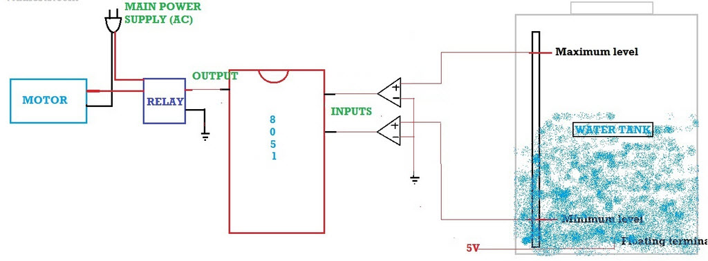
. The sensing is done with a. Then we use the water level to control when to shutdown a. A constant 5v power supply is given to the microcontroller and rest of the circuit from a battery.
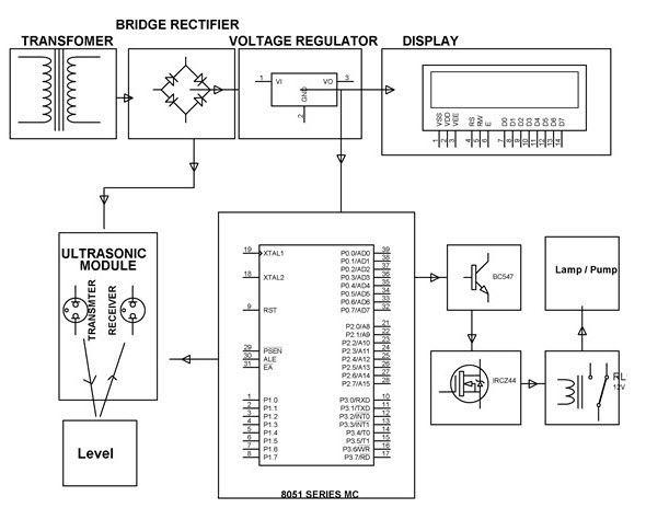
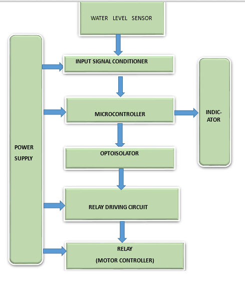
The water level indicator circuit consists of a transistor element and a buzzer which indicates the overflow of water or excessive water in the container whe. The working of the complete water level indicator project is shown in below block diagram. Flexible Automatic Water Level Controller and Indicator Water is very precious for the living beings.
The circuit can be easily assembled on a general-purpose PCB and enclosed in a wooden box. Download scientific diagram Block diagram of water level controller from publication. Circuit Diagram and Explanation As shown in the water level controller circuit given.
Water level indicator circuit. This is the circuit diagram and description for water level indicator. When the water level.
In this post we will create the water level detector block diagram. Water sensing is accomplished. However we are utilising an 8051 microcontroller to construct a circuit that detects and controls the water level in an overhead tank automatically.
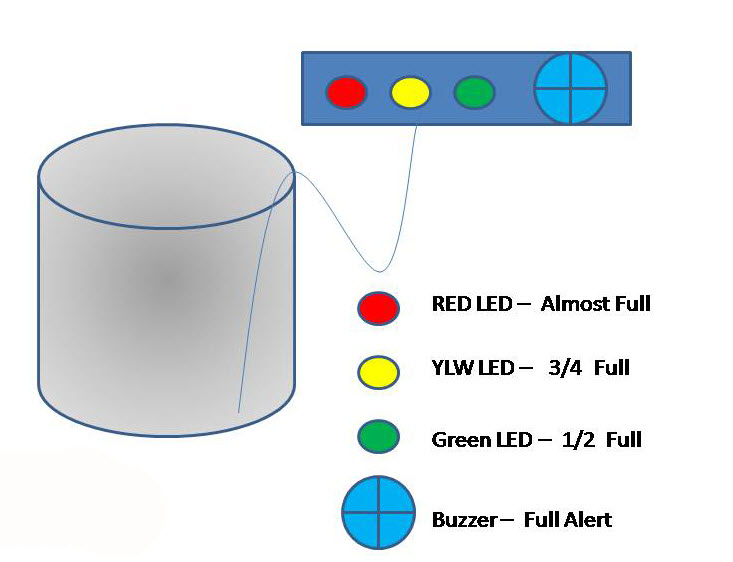
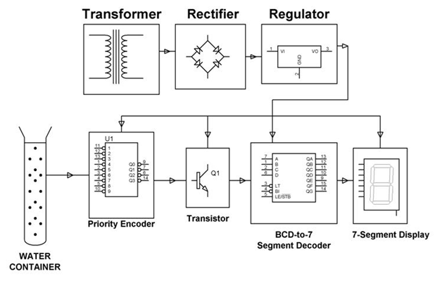
The sensing is done by using a. The Water Level Indicator employs a simple mechanism to detect and indicate the water level in an overhead tank or any other water container. The water level of the tank is indicated by using the 5 LEDs and if the water level in the tanker is full then the water pump is turned off completely.
The Water Level Indicator detects and indicates the water level in an overhead tank or some other water container using a simple mechanism. This system is indicated three levels of water stored in the tank. The tank has 9 conductive.
The tank is semi-transparent so its easy to monitor the. The three LEDs should be mounted on the front. Indicator section for indicating the water level present in the tank and Alarm section for alerting the people to turn off the pump once the tank is completely filled.
The following diagram shows. 25 low but not empty 50 half and 100 full but not overflowing.

Application Of Water Level Measurement With It S Plc Logic
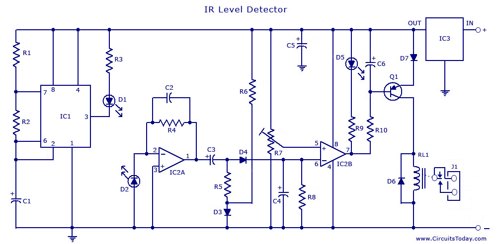
Infrared Ir Sensor Circuit Detector Circuit Diagram Using 555 Ic

Lm339 Circuit How To Make Water Level Indicator

Lm339 Circuit How To Make Water Level Indicator

Sump Pump Aquaponics Sump Pump Aquaponics Groundwater

33 Buckets 33 Buckets Human Centered Design In Chlorine Disinfection
Water And Liquid Level Controller Along With Indicators
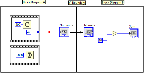
More Breakpoint Weirdness Labview General Lava

Application Of Water Level Measurement With It S Plc Logic

Application Of Water Level Measurement With It S Plc Logic
What Is Water Level Controller Types And Their Working Principles
Water And Liquid Level Controller Along With Indicators

Application Of Water Level Measurement With It S Plc Logic

Lm339 Circuit How To Make Water Level Indicator
Water And Liquid Level Controller Along With Indicators

Sump Pump Aquaponics Sump Pump Aquaponics Groundwater
Application Of Water Level Measurement With It S Plc Logic